
HBT Electric-Motor Group
HBT40S-10-45, HBT50S-12-55, HBT60S-13-90 and HBT80S-13-110 list 40, 50, 60 and 80 m³/h theoretical output. Their motor powers are 45, 55, 90 and 110 kW. Confirm the electrical package and available site supply together.
Concrete Pumps
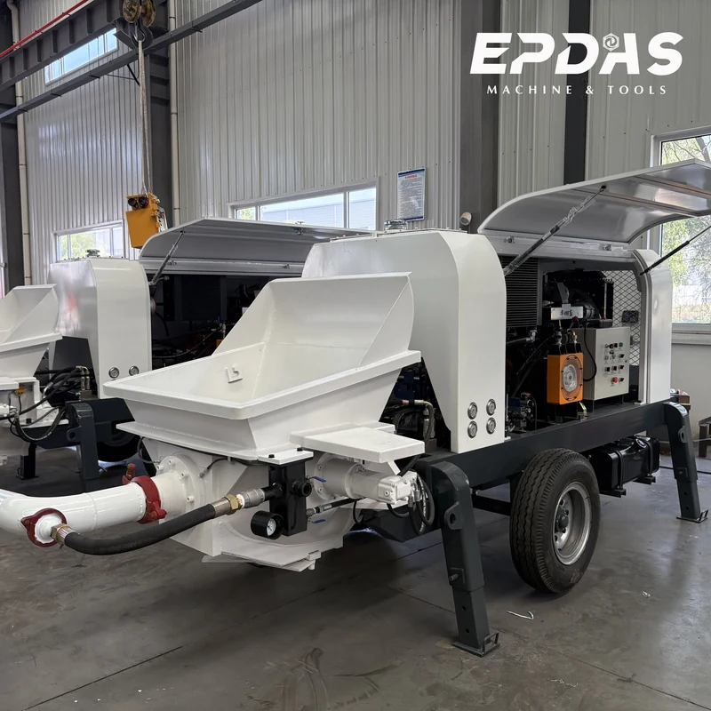
Compare four HBT electric and four DHBT diesel trailer-pump configurations, with theoretical outputs of 40–80 m³/h and separate model-specific pressure and delivery-distance entries.
Model data is supplied by the client. Configuration and operating conditions need confirmation for your order.
01 / Overview
A trailer concrete pump receives prepared concrete and conveys it through a delivery line. It is a pumping unit rather than a concrete batching plant or an integrated mixer. Selection begins with the concrete supply, pipe route and intended rate of placement.
EPDAS documents four HBT electric-motor models and four DHBT diesel models. Their theoretical outputs span 40–80 m³/h. The tables separately identify pressure, vertical and horizontal delivery entries, motor or engine power and machine dimensions.
A trailer chassis helps define the equipment format. It does not establish public-road towing approval or the requirements for transport in a particular destination.
02 / Configurations
HBT40S-10-45, HBT50S-12-55, HBT60S-13-90 and HBT80S-13-110 list 40, 50, 60 and 80 m³/h theoretical output. Their motor powers are 45, 55, 90 and 110 kW. Confirm the electrical package and available site supply together.
The four DHBT models list 60 or 80 m³/h output, with engine powers of 118–174 kW. Models carrying similar output entries can have different pressure entries, so compare the full column rather than output alone.
03 / Specifications
Both original technical matrices are retained. In the electric group, HBT60S-13-90 and HBT80S-13-110 list 12.5 MPa delivery pressure; the model name does not replace the numeric row. Review the exact configuration in the supply specification.
| Items | Units | HBT40S-10-45 | HBT50S-12-55 | HBT60S-13-90 | HBT80S-13-110 |
|---|---|---|---|---|---|
| Theoretical max. discharging volume | m³/h | 40 | 50 | 60 | 80 |
| Theoretical max. delivery pressure | Mpa | 10 | 12 | 12.5 | 12.5 |
| Delivery distance Vertical | m | 120 | 150 | 180 | 180 |
| Delivery distance Horizontal | m | 300 | 350 | 700 | 700 |
| Distribution valve type | S valve | S valve | S valve | S valve | |
| Hopper capacity | L | 600 | 600 | 600 | 600 |
| Feeding height | mm | 1400 | 1400 | 1400 | 1400 |
| Inner dia. of delivery pipe | mm | Φ125 | Φ125 | Φ125 | Φ125 |
| Main motor power | Kw | 45 | 55 | 90 | 110 |
| Dimension (length ×width ×height) | mm | 4970×1680×2580 | 5270×2000×1840 | 6170×1800×2100 | 6170×1930×2100 |
| Overall weight | Kg | 3200 | 3500 | 5100 | 5200 |
| Items | Units | DHBT60-13-118 | DHBT60-16-145 | DHBT80-13-145 | DHBT80-16-174 |
|---|---|---|---|---|---|
| Max. Theoretic delivery volume | m³/h | 60 | 60 | 80 | 80 |
| Max. Theoretic delivery pressure | Mpa | 12.5 | 15.7 | 12.5 | 15.7 |
| Max. Theoretic delivery height | m | 180 | 250 | 180 | 250 |
| Max. Theoretic delivery distance | m | 700 | 1000 | 700 | 1000 |
| Type of distribution valve | S valve | S valve | S valve | S valve | |
| Hopper capacity | L | 600 | 600 | 600 | 600 |
| Inner diameter of delivery pipe | mm | Φ125 | Φ125 | Φ125 | Ф125 |
| Diesel engine power | Kw | 118 | 145 | 145 | 174 |
| Max. Oil pressure of main system | MPa | 32 | 32 | 32 | 32 |
| Max. Oil pressure of mixing system | MPa | 14 | 14 | 14 | 14 |
| Dimension (length ×width ×height) | mm | 6600×1930×2190 | 6600×1930×2190 | 6600×1930×2190 | 6600×1930×2190 |
| Overall weight | Kg | 5500 | 6000 | 6000 | 6500 |
All pumping output and distance entries are theoretical. Maximum pressure, output, horizontal distance and height are separate limits; the concrete and project pipeline require technical assessment.
04 / components
Both groups list a 600 L receiving hopper and S distribution valve. The hopper is part of receiving and feeding concrete into the pumping system; its volume is not the output per pumping stroke.
The source specifies a 125 mm delivery-pipe inner diameter. Diameter alone does not confirm the pressure rating, wall condition, couplings or suitability of a complete delivery line.
Electric motor power and diesel engine power are shown in separate tables. The diesel table also separates main-system and mixing-system oil pressures from concrete delivery pressure.
05 / Working principle
Prepared concrete is supplied to the receiving hopper. The pumping mechanism moves suitable material through a distribution system and into the delivery pipe, while the receiving and placing operations must remain coordinated.
The line determines where concrete arrives; a trailer pump does not include an articulated placing boom simply because it can pump over distance. The arrangement at the delivery end is a separate part of project planning.
This is a general process description. Operating steps, cleaning and any intervention on the equipment or line require the applicable manual and qualified personnel.
06 / constraints
The electric table lists horizontal delivery entries of 300–700 m and vertical entries of 120–180 m. The diesel group lists theoretical distances of 700–1,000 m and heights of 180–250 m. These figures do not certify a particular project route.
Higher pressure entries do not mean maximum output and maximum distance occur simultaneously. Elevation, line length, bends and the concrete’s pumping characteristics must be evaluated for the actual configuration.
07 / quality
A larger pump cannot sustain placement without a suitable, continuous concrete supply. Review truck arrival or mixing arrangements and the receiving space before treating a nominal output as a project production rate.
Confirm concrete pumpability against the selected system. The supplied matrices do not provide a complete aggregate-grading, slump or mix-design schedule, so values from another pump page should not be copied into this equipment specification.
08 / Applications
A routed pipeline can be considered where prepared concrete must travel beyond a convenient direct-discharge point. Access at the pump and the ability to support the route are as important as the nominal distance.
Where the final placement area changes, a compatible separate placing boom may be assessed as part of the system. Compatibility, pressure limits and site support need confirmation; a separate boom is not automatically included.
09 / Site planning
The electric group lists a 1,400 mm feeding height. Check the actual receiving arrangement against the supplying equipment and allow room for its approach, discharge and departure.
Review the pump position, delivery-line support, crossing points and placement access as a complete layout. Machine dimensions and trailer format do not replace installation instructions or a transport plan.
10 / environment
For electric units, confirm the connection and starting requirements for the actual motor package. For diesel units, consider fuel supply, exhaust and service access for the operating site.
Residual concrete and wash-water handling need planned locations and approved procedures. Include cleaning resources in the project arrangement instead of leaving them until pumping has finished.
11 / service
Wear occurs in pumping components and in the delivery system. Inspection should cover the items and limits specified in the manual, including line components and connections; this page does not prescribe a troubleshooting or blockage-clearing procedure.
Agree manuals, commissioning assistance, operator familiarization and spare-part support with EPDAS. Maintenance intervals, commercial terms and technical response arrangements remain specific to the order.
12 / investment
The complete cost includes the unit, power arrangements, delivery line, receiving access and cleaning resources. A theoretical long-distance rating is not a list of supplied pipes and accessories.
Compare the required pressure and practical placement rate before paying for a larger package. Include wear parts, line inspection and downtime planning in the ownership comparison without assuming a fixed cost per cubic metre.
13 / FAQ
EPDAS identifies specialized manufacturing bases for the relevant equipment families.
Pending confirmation. Model-specific inspection and certification evidence remains to be confirmed.
Discuss the documented configuration with EPDAS and review how it fits your concrete supply and placement plan. Final equipment, documentation and support scope are confirmed for the order.
Discuss Trailer Pump ConfigurationsREQUEST A QUOTE