

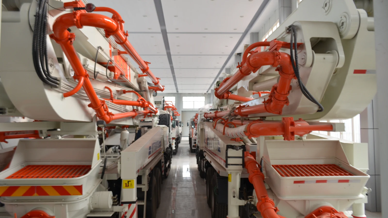
Concrete Pumps
Concrete Boom Pump
Compare HBC28, HBC33, HBC37 and HBC47 truck-mounted concrete pump configurations, with distinct pumping, folding-boom and chassis parameters.
- HBC28 / HBC33 / HBC37 / HBC47
- 60–140 m³/h listed theoretical maximum-output entries
- Model-specific boom and pumping-system parameters
Model data is supplied by the client. Configuration and operating conditions need confirmation for your order.
Overview
A concrete boom pump combines a pumping system with a truck-mounted articulated boom that carries the delivery line towards the placement area. Its suitability depends on reaching the intended location from a feasible setup position while maintaining a suitable concrete supply.
The EPDAS HBC range here covers HBC28, HBC33, HBC37 and HBC47. The supplied matrix separates pumping-system entries, boom geometry and chassis data. Four-section M folding and five-section RZ folding configurations are documented.
The boom model designation alone is not an operating envelope. Review the reach drawing, unfolding requirements and support arrangement for the actual machine before choosing a configuration.
Compare Folding Arrangement and Working Position
Four- and Five-Section Booms
HBC28 lists four boom sections with M folding. HBC33, HBC37 and HBC47 list five sections with RZ folding. These entries describe different arrangements; section count alone does not establish access beneath a roof or around an obstruction.
Horizontal Placement Requirement
The documented horizontal distances are 23.95, 28, 30.9 and 41.2 m. The actual reachable placement area depends on the permitted setup and boom geometry, rather than a circular area inferred from a single distance.
EPDAS HBC Boom Pump Specifications
The source table contains two rows both labelled “Placing depth”, with different values. Their intended definitions remain unresolved. Both rows are retained exactly; neither is silently relabelled as certified vertical height or depth. Obtain the model-specific reach drawing to clarify them.
| Model | Model | Model | HBC28 | HBC33 | HBC37 | HBC47 |
|---|---|---|---|---|---|---|
| Item | Item | Unit | Parameters | Parameters | Parameters | Parameters |
| Pumping system | Max. theory output | m3/h | 68-90 | 60-92 | 80-120 | 140 |
| Pumping system | Theoretic pumping pressure | MPa | 7-8 | 7-8 | 8-14 | 8.5 |
| Pumping system | Theoretical Pumping Times | 26, 24 times/min | 26, 24 times/min | 28,18 times/min | 25 times/min | |
| Pumping system | Concrete Cylinder Diameter * Stroke | mm | φ230*1600 | φ230*1600 | φ230*1650 | φ260*1800 |
| Pumping system | Distribution valve | S valve | S valve | S valve | S valve | |
| Placing boom | Placing depth | m | 27.3 | 32.2 | 36.5 | 46.3 |
| Placing boom | Horizontal distance | m | 23.95 | 28 | 30.9 | 41.2 |
| Placing boom | Placing depth | m | 16.9 | 20.8 | 25.1 | 32 |
| Placing boom | Boom Qty. & Folding Type | 4 & M | 5 & RZ | 5 & RZ | 5 & RZ | |
| Placing boom | End hose length | mm | 2800 | 3000 | 3000 | 3000 |
| Chassis and the whole machine | Chassis brand | DONGFENG | DONGFENG | SINOTRUK | SINOTRUK | |
| Chassis and the whole machine | Wheelbase | mm | 5000 4*2 | 5100 4*2 | 4700+1350 6*4 | 4750+1350 6*4 |
| Chassis and the whole machine | Engine power | HP/ KW | 236/ 174 | 270/ 198 | 310/ 228 | 350/ 257 |
| Chassis and the whole machine | Engine emission | EU-VI | EU-VI | EU-VI | EU-VI | |
| Chassis and the whole machine | Total weight | kg | 19850 | 20000 | 23000 | 35000 |
| Chassis and the whole machine | (L×W×H) Overall dimension | mm | 10000×2450×3650 | 10120×2450×3700 | 9800×2500×3530 | 11700×2500×3900 |
Theoretical pumping values and geometric entries are separate limits. Duplicate source boom labels remain unresolved; approved reach drawings, support data and actual chassis documentation are required for selection.
Pump, Boom and Vehicle Systems
Concrete Pumping Package
The pumping section lists an S valve, cylinder dimensions, stroke-rate entries and theoretical output/pressure values. Where ranges appear, they do not establish a continuous combination of maximum flow and maximum pressure.
Boom and End Hose
The articulated structure positions its delivery pipe. End-hose lengths are listed separately: 2,800 mm on HBC28 and 3,000 mm on the other three models. A listed hose length does not authorize extensions or added tip loads.
Truck Chassis
The source includes chassis options, wheelbase, engine and overall vehicle dimensions. Confirm the exact chassis and final installed configuration in the order, including the relevant transport documentation.
How Pumping and Boom Placement Interact
Prepared concrete is supplied to the pump’s receiving system and conveyed through pipework carried by the boom. The boom changes the position of the delivery end within its approved envelope; the pump provides concrete movement through the line.
These are related but separate functions. A longer boom does not automatically provide a higher placement rate, and a high theoretical pump output does not resolve access to a restricted placement point.
This explains the general arrangement. Setup, boom movement, concrete delivery and cleaning must follow the actual machine’s manual and the site’s trained operating arrangements.
Use the Approved Envelope and Support Arrangement
A workable setup needs space for the vehicle and its required supports, suitable ground and clearance from obstacles. The supplied matrix does not give a complete outrigger spread or support-load schedule; those details must be obtained for the selected model.
Do not infer partial-support permissions, unrestricted rotation or below-grade capability from the table or a photograph. A site-specific lift and placement plan must use the applicable machine information.
Balance Pump Delivery with Concrete Supply
The table lists theoretical output entries of 68–90, 60–92, 80–120 and 140 m³/h by model. These describe the pumping specification, not a guaranteed completed-pour rate. Supplying trucks, material consistency and the placement crew can limit practical output.
Review pumpability and concrete acceptance with the producer and project team. A boom positions the line; it does not correct unsuitable concrete or replace proportioning and quality control.
Evaluate Placement from a Truck Setup Point
Construction and Foundation Work
A truck-mounted boom can be assessed for placing prepared concrete where the setup position and working envelope allow the delivery line to approach the pour. Review the building geometry and the available approach before selecting a reach class.
Projects with Restricted Vehicle Access
Where truck access is impractical, a separate line pump or placing boom may deserve comparison. This does not establish that any alternative fits the project; it identifies a different arrangement to assess.
Plan Vehicle Access and Unfolding Space
Check gateways, turning approaches, overhead restrictions and the vehicle’s installed dimensions. The HBC entries span different wheelbase and overall-length configurations, so access should be checked for the selected truck.
A boom must also unfold and move without relying on a nominal reach number alone. Confirm unfolding height, obstacle clearance, setup position and receiving-truck access from the relevant drawings.
Chassis Documentation and Washout Planning
The source describes EU-VI engine emission entries. Treat these as supplied configuration descriptions, not proof of registration or environmental approval for every destination. Verify the exact vehicle and its supporting documentation.
Arrange concrete washout and cleaning-water management at the site. The operating area needs sufficient room for the supply and placement equipment as well as the resources needed after the pour.
Maintain the Structural and Pumping Systems
Boom structure, supports, hydraulics, pipework and pumping wear parts require the inspections specified for the actual machine. A general product page cannot replace structural inspection criteria or authorize repair methods.
Discuss manuals, inspection documentation, commissioning, training and spare parts with EPDAS. Chassis support and pump support should be clear in the supply agreement rather than assumed to be one unrestricted service commitment.
Compare Reach with a Feasible Setup
The useful comparison is the configuration that can serve the placement area from an approved support position. A larger nominal boom may bring different access, transport and support requirements as well as a different initial price.
Include chassis specification, wear parts, inspections and logistics in the ownership plan. No fixed fuel saving, setup time or cost per pour is established by the available matrix.
Frequently Asked Questions
Which HBC models are shown?
The supplied range is HBC28, HBC33, HBC37 and HBC47.
Do all models use the same folding boom?
No. HBC28 lists four sections with M folding. The other three list five sections with RZ folding.
What horizontal distances are listed?
The source lists 23.95, 28, 30.9 and 41.2 m respectively. Confirm the usable envelope from the selected machine’s drawing.
Are the two “Placing depth” rows resolved?
No. The source repeats that label with different values. Both are retained and need clarification against model-specific reach drawings.
Does maximum output mean the actual pour rate?
No. It is theoretical pumping data; concrete supply, line conditions and placement demand affect actual output.
Can maximum flow and pressure be assumed together?
No. The table does not establish that combination. Obtain the relevant performance data for the configured pump.
What end-hose length is shown?
HBC28 lists 2,800 mm; HBC33, HBC37 and HBC47 list 3,000 mm. Any changed hose arrangement requires approval.
Are support loads and outrigger spread supplied here?
Not as a complete setup schedule. Obtain the machine-specific support information before planning installation.
Does the engine label establish road approval?
No. Verify the actual chassis, emission documents and registration requirements for the destination.
Does a longer boom replace a site survey?
No. Access, supports, ground, unfolding clearance and the placement envelope all need assessment.
Manufacturing & product evidence
EPDAS identifies specialized manufacturing bases for the relevant equipment families.
Pending confirmation. Model-specific inspection and certification evidence remains to be confirmed.
Compare an EPDAS Boom Pump Around Your Setup Position
Discuss the documented configuration with EPDAS and review how it fits your concrete supply and placement plan. Final equipment, documentation and support scope are confirmed for the order.
Discuss HBC Configurations