
Telescopic Handler Forklifts
Telehandler
Compare nine documented EPDAS telehandlers, with maximum rated loads of 2.5–7 t and maximum lift heights of 6–18 m across models, including configurations with and without outriggers.
- 2.5–7 t maximum rated load across models
- 6–18 m maximum lifting height across models
- Models with and without outriggers
Model data is supplied by the client. Configuration and operating conditions need confirmation for your order.
Overview
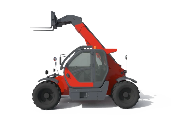
A telehandler combines a telescopic boom with a material-handling attachment to position loads at different heights and forward distances. For a construction project or materials yard, its value depends on reaching the required placement point with the permitted load, rather than simply having the largest number on a specification sheet.
The EPDAS range presented here contains two documented groups: five models with outriggers and four without. The tables distinguish rated load, maximum lifting height, boom sections, controls, tyres and dimensions. These differences help narrow the choice before reviewing an actual handling task.
Maximum load and maximum lift height are separate ratings. This page does not provide a model-specific load chart or a promise of capacity at maximum extension.
Choose the Boom and Support Configuration
Models with Outriggers
T3512, T4014, T5010, T5018 and T7018 form the outrigger-equipped group. Their listed maximum loads are 3.5, 4, 5, 5 and 7 t respectively. Maximum heights are 12, 14, 10, 18 and 17.6 m. The T7018 designation should therefore not be read as an exact 18 m rating.
Models without Outriggers
T2506, T3007, T3507 and T4007 are listed without outriggers, with maximum loads of 2.5, 3, 3.5 and 4 t. Their maximum heights are 6, 7, 7 and 7 m. Compare the complete dimensions and the required working envelope when considering these configurations.
EPDAS Telehandler Model Specifications
Both original model tables are retained below. Read one complete model column at a time, including its support arrangement and control specification. Source-listed options require confirmation for the equipment supplied to your destination.
| Model | T3512 | T4014 | T5010 | T5018 | T7018 |
|---|---|---|---|---|---|
| Load | Max. 3.5t | Max. 4t | Max. 5t | Max. 5t | Max. 7t |
| Lifting Height | Max. 12m | Max. 14m | Max. 10m | Max. 18m | Max. 17.6m |
| Engine Power | 85KW/114 HP | 85KW/114 HP | 91KW/122 HP | 91KW/122 HP | 119KW/160 HP |
| Emission Standards | Stage Ⅱ Options: StageⅢ, StageⅤ, EPA 4 | Stage Ⅱ Options: StageⅢ, StageⅤ, EPA 4 | Stage Ⅱ Options: StageⅢ, StageⅤ, EPA 4 | Stage Ⅱ Options: StageⅢ, StageⅤ, EPA 4 | Stage Ⅱ Options: StageⅢ, StageⅤ, EPA 4 |
| Axles & Braking | Wet type with Oil-immersed Electric Brake | Wet type with Oil-immersed Electric Brake | Wet type with Oil-immersed Electric Brake | Wet type with Oil-immersed Electric Brake | Wet type with Oil-immersed Electric Brake |
| Hydraulic Transmission | Torque Converter & Gear Pump | Torque Converter & Gear Pump | Torque Converter & Gear Pump | Torque Converter & Gear Pump | Torque Converter & Gear Pump |
| Hydraulic Operation | Load-sensitive Vavel + Electro-hydraulic Proportional Handle System | Load-sensitive Vavel + Electro-hydraulic Proportional Handle System | Load-sensitive Vavel + Electro-hydraulic Proportional Handle System | Load-sensitive Vavel + Electro-hydraulic Proportional Handle System | Load-sensitive Vavel + Electro-hydraulic Proportional Handle System |
| Moment limiter | √ | √ | √ | √ | √ |
| Boom Configuration | 3 Sections | 3 Sections | 3 Sections | 4 Sections | 4 Sections |
| Tires | Pneumatic-tires (16/70-24) | 400/80R24 Tubeless Tire | 400/80R24 Tubeless Tire | 400/80R24 Tubeless Tire | 17.5-25 Tubeless Tire |
| Dimensions | 5800*2200*2550mm | 6400*2350*2550mm | 6400*2350*2550mm | 6600*2350*2650mm | 6880*3650*2800mm |
| Self-leveling Forks | 1220*150*50mm (L*W*T) | 1220*150*50mm (L*W*T) | 1220*125*50mm (L*W*T) | 1220*125*50mm (L*W*T) | 1220*150*50mm (L*W*T) |
| Model | T2506 | T3007 | T3507 | T4007 |
|---|---|---|---|---|
| Load | Max. 2.5t | Max. 3t | Max. 3.5t | Max. 4.0t |
| Lifting Height | Max. 6m | Max. 7m | Max. 7m | Max. 7m |
| Engine Power | 58KW/78HP | 76KW/102 HP | 76KW/102 HP | 85KW/114 HP |
| Emission Standard | Stage Ⅱ Options: StageⅢ, StageⅤ, EPA 4 | Stage Ⅱ Options: StageⅢ, StageⅤ, EPA 4 | Stage Ⅱ Options: StageⅢ, StageⅤ, EPA 4 | Stage Ⅱ Options: StageⅢ, StageⅤ, EPA 4 |
| Axles & Braking | Dry type with Air-cut brake | Dry type with Air-cut brake | Dry type with Air-cut brake | Wet type with Oil-immersed Electric Brake |
| Hydraulic Transmission | Torque Converter & Gear Pump | Torque Converter & Gear Pump | Torque Converter & Gear Pump | Torque Converter & Gear Pump |
| Hydraulic Operation | Hydraulic Pilot Handle System | Hydraulic Pilot Handle System | Hydraulic Pilot Handle System | Load-sensitive Vavel + Electro-hydraulic Proportional Handle System |
| Moment limiter | ✘ | ✘ | √ | √ |
| Boom Configuration | 2 Sections | 2 Sections | 2 Sections | 2 Sections |
| Tires | 12-16.5 Tubeless Tire | Pneumatic-tires (16/70-20) | Pneumatic-tires (16/70-20) | 400/70-24 Tubeless Tire |
| Dimensions | 4000*2020*2050mm | 4650*2200*2550mm | 4650*2200*2550mm | 4650*2200*2550mm |
| Self-leveling Forks | 1220*150*50mm (L*W*T) | 1220*150*50mm (L*W*T) | 1220*150*50mm (L*W*T) | 1220*150*50mm (L*W*T) |
Table entries retain the supplied model data. Rated load, lift height and other maxima are separate values; confirm permitted capacity for the actual load, attachment and operating configuration using the applicable documentation.
Boom, Controls and Handling Equipment
Telescopic Boom
The range includes two-, three- and four-section booms. Section count describes the telescoping structure; it does not establish the available load at a particular reach. Match the actual attachment and intended placement geometry to the appropriate chart.
Transmission and Hydraulic Controls
Torque-converter and gear-pump transmission entries appear in both groups. Hydraulic pilot handles are listed on T2506 and T3007, while the other documented models list load-sensitive valves and electro-hydraulic proportional handles. Controls should be reviewed for the selected machine, not assumed identical across the range.
Forks and Attachments
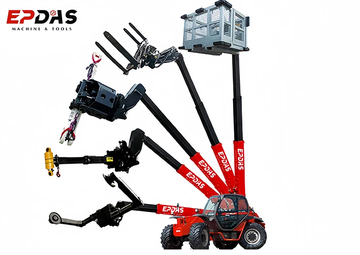
The supplied fork dimensions and attachment illustrations support an equipment discussion. An illustrated bucket, carriage or other tool is not confirmation that it is included or approved for every model.
How Telescopic Material Placement Works
The boom provides changes in height and forward position, while the fitted tool supports or handles the material. A handling task connects the load, its centre of gravity, the attachment and the required placement point.
A conventional mast forklift primarily raises a carriage along a mast. A telescopic boom adds forward reach to the selection problem. Choosing between the two involves access to the load and placement point as well as capacity.
This is a general explanation of equipment function. Operator training, movement sequences and machine setup must follow the documentation for the actual telehandler.
Evaluate Capacity at the Required Reach
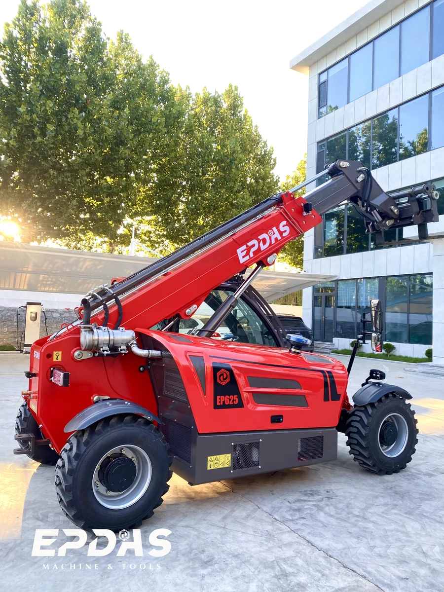
Compare the planned task with the load chart for the machine and attachment combination. Do not combine the highest rated load from one row with the highest lift or reach from another. A photograph of an extended boom cannot establish what that configuration may lift.
Outrigger position, supporting conditions and the configuration identified on the chart matter. A model supplied without outriggers cannot be assessed using an outrigger-equipped model’s envelope. Where the task cannot be verified from the applicable documentation, resolve it before selecting the machine.
Review Load Information and Limiter Availability
The tables mark a moment limiter on all five outrigger-equipped models and on T3507 and T4007. T2506 and T3007 are marked without one. Keep this distinction visible during model comparison; the device is not a standard feature of every listed telehandler.
A limiter entry does not replace a load chart, a correctly identified attachment or an assessment of the load. Confirm the actual equipment, documentation and inspection condition before bringing a machine into service.
Where a Telehandler May Fit
Construction and Materials Yards
Construction material placement can involve pallets or components that must be positioned beyond the truck’s immediate front edge. A telehandler can be assessed for such work when the load, reach, access and support requirements are known.
Tasks Requiring a Different Tool
Different tools may support different handling tasks, but compatibility and capacity need confirmation for each combination. Attachment pictures are selection references, not approval to lift people, suspend loads or perform another specialized operation.
Plan Access and the Working Area
Check gateways, overhead obstacles, approach space and the machine’s working position. The dimension rows vary considerably between models. Confirm how those dimensions are measured and allow for attachments and any deployed supports.
Review the ground and any floor or structure supporting the loaded machine. Tyre type and machine size alone do not establish suitability for every surface or slope. Keep the working area and traffic arrangements consistent with the site assessment.
Engine Options and Site Conditions
The source lists Stage II with Stage III, Stage V and EPA 4 options. These are source descriptions of potential configurations, not evidence that every machine holds every listed approval. Verify the engine supplied and the documentation applicable to the destination.
Discuss dust, weather, surface condition and the intended working environment when finalizing the equipment. No universal road registration, enclosed-space suitability or environmental certification is implied.
Documentation, Inspection and Support
The selected telehandler needs its relevant manual, capacity information and attachment documentation. Review fork condition, boom components, hydraulic equipment and other inspection requirements through the manufacturer’s prescribed maintenance process.
EPDAS can discuss the training, spare parts and technical support scope for the order. Availability, delivery arrangements and warranty terms must be agreed for that equipment; a general product description is not a service commitment.
Compare the Complete Handling Package
Purchase comparisons should cover the machine, required attachments, transport and the resources needed to put it into service. The cost of a higher-reaching model may not be justified if the intended tasks stay within a smaller machine’s verified envelope.
Compare working-area requirements and recurring maintenance alongside the initial price. A suitable choice connects the actual placement task to a documented configuration without relying on an unsupported capacity assumption.
Frequently Asked Questions
Which EPDAS telehandler models are shown?
Five outrigger-equipped models—T3512, T4014, T5010, T5018 and T7018—and four without outriggers—T2506, T3007, T3507 and T4007—are detailed in the two tables.
What maximum load range is listed?
The documented models span maximum rated loads from 2.5 to 7 t. The permitted load for a particular task depends on its model-specific chart and configuration.
What lifting heights are listed?
Maximum heights across the models range from 6 to 18 m. T5018 lists 18 m; T7018 lists 17.6 m. These figures do not establish capacity at those heights.
Can maximum load be lifted at maximum boom extension?
Do not assume so. Verify the load, height, reach and attachment combination against the chart for the actual machine.
Do all models have outriggers?
No. The first table covers models with outriggers; T2506, T3007, T3507 and T4007 are listed without them.
Is a moment limiter listed on every model?
No. T2506 and T3007 are marked without a moment limiter. The other seven documented models are marked with one.
Are all illustrated attachments included?
No. Images show equipment options. Inclusion, compatibility and the corresponding capacity information must be confirmed for the order.
Are the control systems the same?
No. T2506 and T3007 list hydraulic pilot handles; other shown models list load-sensitive valves and electro-hydraulic proportional handles.
Are all listed emission options automatically supplied?
No. Source-listed options require confirmation of the actual engine and destination-specific documentation before purchase.
Does this page replace the operating manual?
No. It supports product comparison. Machine setup, operation, inspections and maintenance require the applicable documentation and trained personnel.
Manufacturing & product evidence
EPDAS identifies specialized manufacturing bases for the relevant equipment families.
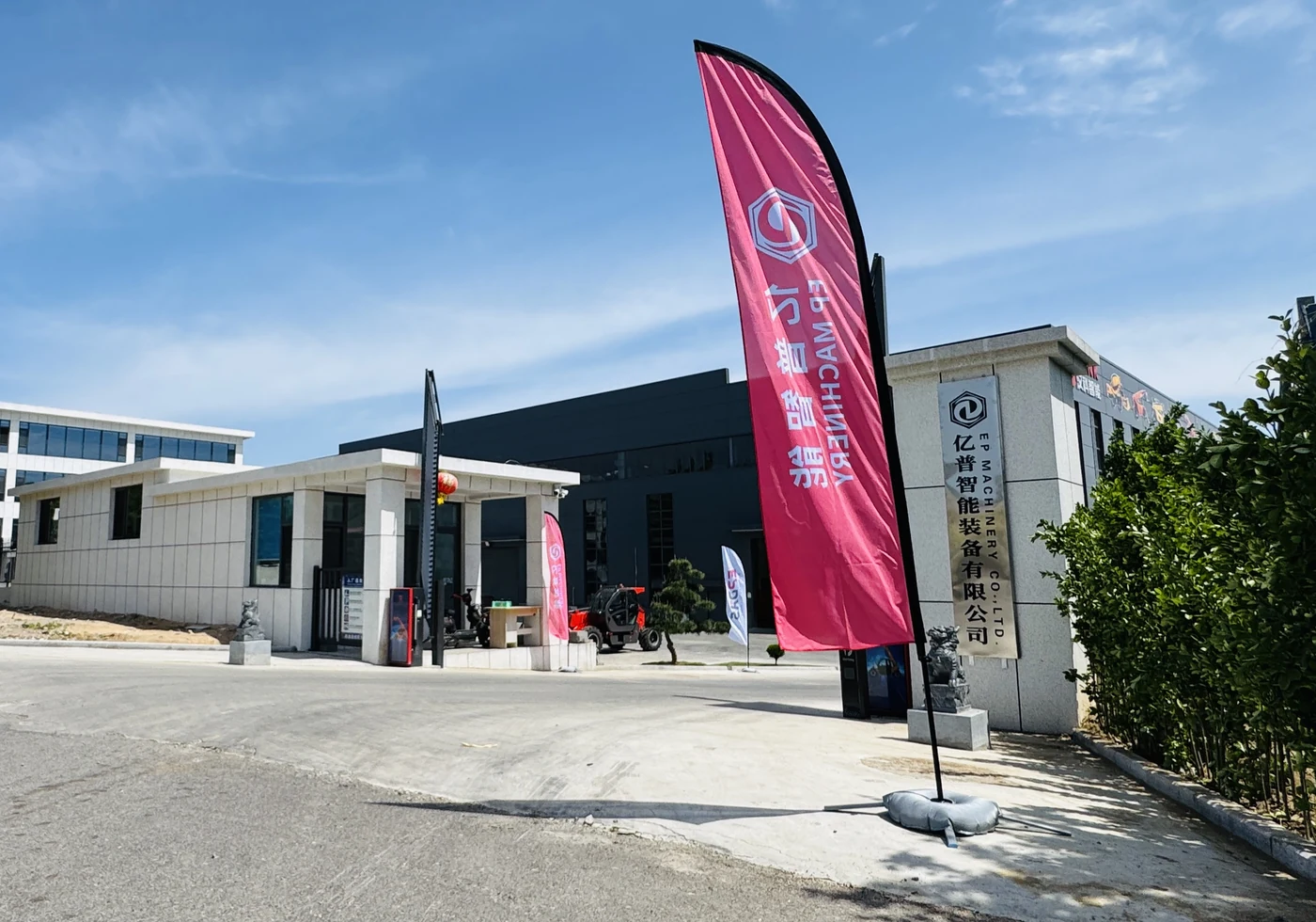
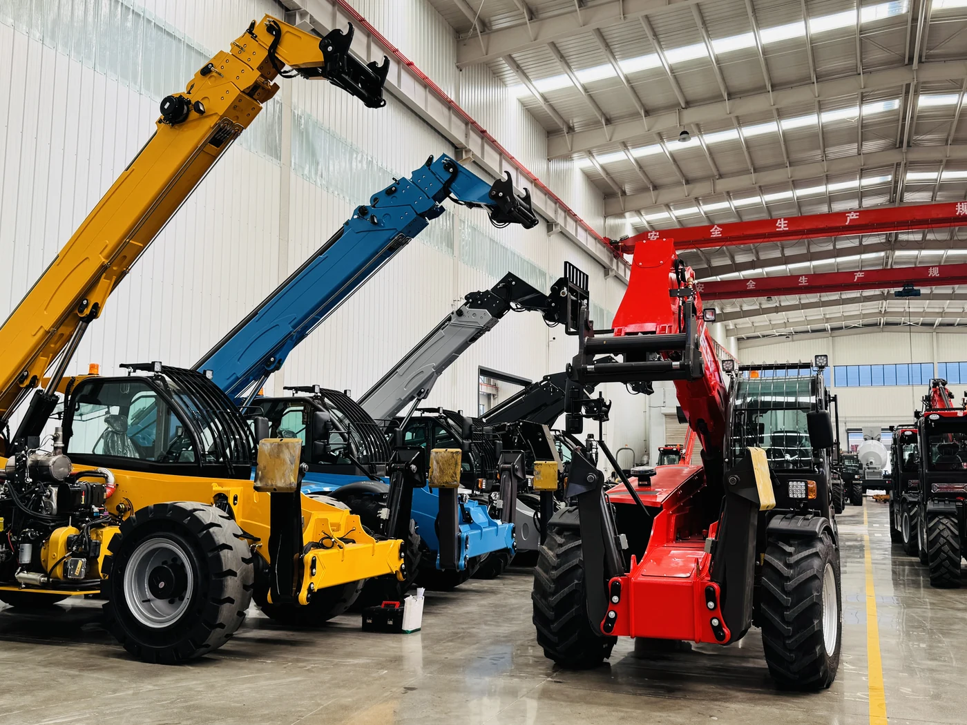
Pending confirmation. Model-specific inspection and certification evidence remains to be confirmed.
Compare an EPDAS Telehandler for Your Placement Task
Discuss the documented configurations with EPDAS and compare the equipment package against your handling operation. Model-specific documentation and the agreed supply scope remain part of the selection.
Discuss Telehandler Configurations