Concrete Pumps
Concrete Mixer Pump
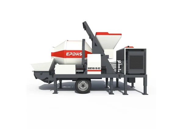
DJBT diesel and EJBT electric configurations combining a 450 L-per-tank mixer entry with 30–48 m³/h theoretical pumping outputs across the documented models.
- 30–48 m³/h theoretical pumping output
- 450 L mixer volume per tank
- Diesel and electric model options
Model data is supplied by the client. Configuration and operating conditions need confirmation for your order.
Overview
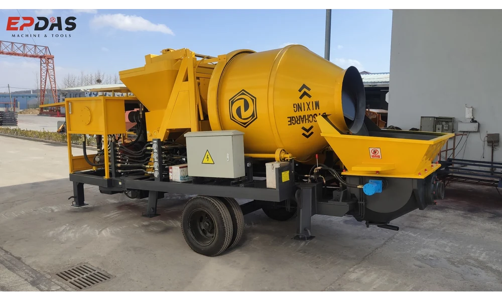
A concrete mixer pump combines concrete mixing with pipeline conveying in one equipment package. It can be considered where a project needs to prepare concrete at the site and move it to a placement point that is not convenient for direct discharge.
The EPDAS range here covers DJBT50-10-85, DJBT40-10-82, DJBT30-08-76 and EJBT30-08-37. Their theoretical pumping outputs are 48, 40, 32 and 30 m³/h respectively. Three configurations use diesel engines; the EJBT model lists a 37 kW electric motor.
Pump displacement and mixing production are different measures. A theoretical pumping value cannot be used as the hourly output of the complete mixing-and-placement operation.
Choose the Power Package and Concrete Supply Method
Diesel DJBT Configurations
The diesel models list 85, 82 and 76 kW engines. They provide a different power arrangement from the electric configuration, but fuel access, servicing and the actual operating environment still need review.
Electric EJBT Configuration
EJBT30-08-37 lists a 37 kW motor. Confirm the required electrical supply, starting arrangement and site connection for the delivered equipment. Motor power alone does not establish compatibility with a particular generator.
EPDAS Mixer Pump Specifications
The original table retains pumping, mixer, hopper, pipe and packing entries. The pressure unit appears as “MP” in the source and needs technical clarification. Keep model-specific values together rather than combining the largest figures from different columns.
| ITEM | ITEM | DJBT50-10-85 | DJBT40-10-82 | DJBT30-08-76 | EJBT30-08-37 |
|---|---|---|---|---|---|
| Theoretical concrete pumping | Theoretical concrete pumping | 48 m³/hr | 40 m³/hr | 32 m³/hr | 30 m³/hr |
| Max. Concrete pumping pressure | Max. Concrete pumping pressure | 10 MP | 10 MP | 8 MP | 8 MP |
| Main engine | Main engine | Diesel engine: YUCHAI 85KW | Diesel engine: WEIFANG 82KW | Diesel engine: WEIFANG 76KW | Electric motor: 37KW |
| Main oil pump | Main oil pump | KAWASAKI 112 | KAWASAKI 112 | KAWASAKI 112 | JINDA |
| Main oil cylinder diameter/stroke | Main oil cylinder diameter/stroke | Φ100/800 mm | Φ100/800 mm | Φ90/580 mm | Φ90/580 mm |
| Concrete cylinder diameter/stroke | Concrete cylinder diameter/stroke | Φ180/800 | Φ180/800 | Φ180/580 mm | Φ180/580 mm |
| Theoretical pump distance | Theoretical pump distance | Height: 70 m Length: 250 m | Height: 60 m Length: 250 m | Height: 50 m Length: 200 m | Height: 50 m Length: 200 m |
| Hydraulic pump set | Hydraulic pump set | HUADE (CN) | HUADE (CN) | HUADE (CN) | HUADE (CN) |
| Hydraulic valve set | Hydraulic valve set | TAIFENG (CN) | TAIFENG (CN) | TAIFENG (CN) | TAIFENG (CN) |
| Lubricating system | Lubricating system | Automatic hydraulic | Automatic hydraulic | Automatic hydraulic | Automatic hydraulic |
| Concrete mixer volume | Concrete mixer volume | 450L per tank | 450L per tank | 450L per tank | 450L per tank |
| Max. Aggregate size | Max. Aggregate size | 35 mm | 35 mm | 35 mm | 35 mm |
| Aggregate lifting volume | Aggregate lifting volume | 500L per hopper | 500L per hopper | 500L per hopper | 500L per hopper |
| Concrete slump | Concrete slump | 160-220 mm | 160-220 mm | 160-220 mm | 160-220 mm |
| Controller | Controller | Wireless / Cabinet-buttons | Wireless / Cabinet-buttons | Wireless / Cabinet-buttons | Wireless / Cabinet-buttons |
| Main electric components | Main electric components | CHINT (CN) | CHINT (CN) | CHINT (CN) | CHINT (CN) |
| Machine weight | Machine weight | 5400 kg | 5300 kg | 5200 kg | 5000 kg |
| Machine Dimension | Integrated (20GP pack) | 4500*2100*2300 | 4500*2100*2300 | 4500*2100*2300 | 4500*2200*2800mm |
| Machine Dimension | Split type (40HQ pack) | 5600*2100*2300 | 5600*2100*2300 | 5600*2100*2300 | / |
| Diameter of concrete pipe | Diameter of concrete pipe | Φ125 mm | Φ125 mm | Φ125 mm | Φ125 mm |
| Length of concrete pipe | Length of concrete pipe | 100 m | 100 m | 100 m | 100 m |
Theoretical pumping output, mixer volume, maximum pressure and delivery distances describe different conditions. Source pressure units and the actual pipeline/concrete combination require technical confirmation.
Mixing, Feeding and Pumping Systems
Mixer and Loading Hopper
All four configurations list 450 L per tank for the mixer and 500 L per hopper for aggregate lifting. These are separate component-volume entries; neither is a verified batch yield or hourly concrete production rating.
Hydraulic Pumping Package
The table lists cylinder dimensions, hydraulic components and automatic hydraulic lubrication. These describe the supplied schedule. They do not establish maintenance-free operation or a universal duty cycle.
Controls and Delivery Line
Wireless and cabinet-button control are listed, together with a 125 mm concrete-pipe diameter. Review the exact control equipment, pipeline components and included accessories for the order.
How Mixing and Pipeline Delivery Work Together
Materials must first be proportioned for the intended concrete. The mixer combines those ingredients, after which the pumping system transfers suitable concrete into the delivery line. Placement follows the supply rate and the requirements at the discharge point.
The process depends on the loading and mixing cycle as well as the pump. If mixed concrete is not available at the required rate, a higher theoretical pump output will not create extra supply.
This describes the general equipment role. Charging, starting, cleaning and intervention procedures must follow the supplied manual and trained operator arrangements.
Interpret Delivery Distance as a Project Calculation
The source lists theoretical horizontal distances of 200–250 m and heights of 50–70 m across the models. These are separate comparison entries, not a promise to achieve both maxima together on an arbitrary route.
Pipeline length, bends, elevation and the concrete itself affect the pumping requirement. Have the planned line and concrete assessed for the selected configuration; the table is not a pipeline design or a pressure-loss calculation.
Match the Concrete to the Pumping Requirement
The table lists a maximum aggregate size of 35 mm and slump of 160–220 mm. These are equipment-source entries, not a complete mix design. Aggregate grading, consistency and the project’s concrete requirements still need review.
Do not add water merely to make material easier to pump without the concrete producer’s approval. Maintain material measurement and quality checks through loading, mixing and placement. An integrated machine does not replace that quality process.
Consider the Entire Site Supply Chain
Site Mixing with Remote Placement
The combined arrangement may be assessed for construction work where site mixing and pipeline delivery are both required. Compare loading access and material storage with the planned discharge location.
When to Compare Other Pump Types
If concrete is already supplied by mixer trucks, a separate trailer pump may be a more relevant comparison. A truck-mounted boom pump addresses another requirement: positioning its delivery line through a boom. These categories should be chosen by the supply task, not only nominal output.
Plan Loading Access and the Delivery Route
Provide working space for materials, loading and the pump receiving area, then review the complete pipeline route. Vehicle access, supports and separation from other site activities should be part of the arrangement.
The table distinguishes integrated and split packing dimensions, with a slash entry for the electric split version. Packing descriptions do not establish the operating footprint, a universal shipping method or approval for towing on public roads.
Power, Washout and Site Arrangements
Assess electricity or fuel needs for the actual equipment, together with the working environment. Diesel and electric packages have different site requirements; neither removes the need for a suitable setup.
Plan where washout, residual concrete and cleaning water will be managed. The supply and placement operation needs enough space to finish the work and clean the equipment under the approved site arrangements.
Wear Parts, Lubrication and Documentation
The mixer, pumping components and delivery line have distinct inspection and maintenance needs. Automatic lubrication does not eliminate checks of wear parts, hoses, couplings and the other components identified in the manual.
Confirm operating documentation, training, spares and support scope with EPDAS. The general description does not fix a maintenance interval, delivery date, warranty duration or response time.
Compare Productive Mixing and Placement Cost
Compare the machine with its power connection, loading resources, delivery line and cleaning arrangements. A useful purchase comparison includes the work required to keep concrete arriving at the pump and being placed at the outlet.
Pipe diameter and a source-listed pipe length do not define the complete included delivery package. Confirm quantities, wear items and accessories in the order instead of treating theoretical distance as supplied pipe length.
Frequently Asked Questions
Which models are listed?
The range is DJBT50-10-85, DJBT40-10-82, DJBT30-08-76 and EJBT30-08-37.
What theoretical pumping outputs are shown?
The four models list 48, 40, 32 and 30 m³/h respectively. Actual mixing and placement rates are separate.
Is the full mixing process rated at 48 m³/h?
No. That is a theoretical pumping entry, not a verified hourly yield from the mixer.
Which version is electric?
EJBT30-08-37 lists a 37 kW electric motor. The three DJBT configurations list diesel engines.
What does the 450 L figure describe?
The source labels it mixer volume per tank. It is not established as concrete output per batch.
Can maximum height and distance be achieved together?
Do not assume so. The planned pipe route and concrete require assessment for the selected pump.
What aggregate and slump values are listed?
The source lists 35 mm maximum aggregate and 160–220 mm slump. These do not constitute a complete approved concrete mix.
What controls are documented?
Wireless and cabinet-button controls appear in all four model columns. Confirm the actual package supplied.
Does automatic lubrication remove maintenance?
No. Follow the manual for inspection, lubrication and wear-component maintenance.
Is the maximum theoretical distance the included pipe length?
No. The table separately lists 100 m of concrete pipe. Confirm actual included quantities and the project line design.
Manufacturing & product evidence
EPDAS identifies specialized manufacturing bases for the relevant equipment families.
Pending confirmation. Model-specific inspection and certification evidence remains to be confirmed.
Plan an EPDAS Mixer Pump Around Your Concrete Supply
Discuss the documented configuration with EPDAS and review how it fits your concrete supply and placement plan. Final equipment, documentation and support scope are confirmed for the order.
Discuss Mixer Pump Configurations