

Concrete Pumps
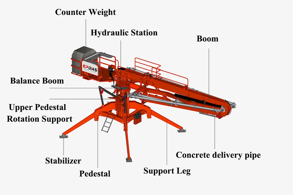
Spider Boom
HGY14, HGY15, HGY17 and HGY21 separate concrete placing booms with listed maximum radii of 14, 15, 17 and 21 m, supplied with model-specific arm and support parameters.
- HGY14 / 15 / 17 / 21
- 14–21 m maximum placing-radius entries
- Model-specific boom-arm parameters
Model data is supplied by the client. Configuration and operating conditions need confirmation for your order.
Overview
A spider boom is a separate concrete placing boom used to position a delivery line within an assessed working area. It works as part of a pumping system; it is not itself a concrete mixer or a complete concrete pump.
The EPDAS HGY range shown here comprises HGY14, HGY15, HGY17 and HGY21. The table records arm lengths, maximum placing radius, rotation, support-leg spans, bare-machine weights and balance-weight entries.
This page concerns concrete placing equipment, not an aerial work platform. Concrete supply, pumping, installation and support must all be reviewed alongside the boom configuration.
Choose the Radius and Support Footprint Together
Four Placing-Radius Entries
Maximum placing radii are 14, 15, 17 and 21 m. These provide a starting point for comparison, but actual access depends on the geometry, setup position and approved operating envelope.
Support and Tail Clearance
The listed support spans increase from 3.15 × 3.15 m on HGY14 to 5 × 5 m on HGY21. Tail-rotation radius also varies. Keep those dimensions in the layout discussion rather than evaluating reach in isolation.
EPDAS HGY Placing Boom Specifications
The complete parameter schedule is retained below. The source labels the control-mode unit as “kg”; that label is ambiguous and does not turn a control description into a weight rating. Clarify the selected configuration and any source-label issue against its technical documentation.
| Item | Unit | Models and parameter | Models and parameter | Models and parameter | Models and parameter |
|---|---|---|---|---|---|
| Item | Unit | HGY14 | HGY15 | HGY17 | HGY21 |
| Max. placing radius | m | 14 | 15 | 17 | 21 |
| Big arm length | m | 5.7 | 6 | 6.66 | 8.66 |
| Big arm elevation | ° | -2~84.4 | 0~70 | 0~65 | 0~65 |
| Medium arm length | m | 4.52 | 5 | 5.73 | 6.73 |
| Medium arm elevation | ° | 0~180 | 0~180 | 0~180 | 0~180 |
| Small arm length | m | 3.78 | 4 | 4.61 | 5.61 |
| Small arm elevation | ° | 0~180 | 0~180 | 0~180 | 0~180 |
| Hose length | m | 3 | 3 | 3 | 3 |
| Concrete delivery pipe | mm | ø125×6 | ø 125×6 | ø 125×6 | ø 125×6 |
| Tail rotary radius | m | 2.72 | 2.81 | 3.51 | 3.93 |
| Total power | Kw | 4 | 4 | 5.5/7.5 | 5.5/7.5 |
| System pressure | Mpa | 24 | 24 | 24 | 24 |
| Rotary speed | r/min | 0.3—0.8 | 0.3—0.8 | 0.3—0.8 | 0.3—0.8 |
| Rotary range | ° | 0~360 | 0~360 | 0~360 | 0~360 |
| Supporting legs span | m | 3.15×3.15 | 4×4 | 4.6×4.6 | 5×5 |
| Overall height | m | 2.9 | 2.6 | 3.2 | 3.75 |
| Bare machine weight | kg | 2700 | 3230 | 5000 | 6700 |
| Balance weight | kg | 2×900 | 2×1100 | 2200 | 2×1100 |
| Control mode | kg | Panel/ Wireless remote control | Panel/ Wireless remote control | Panel/ Wireless remote control | Panel/ Wireless remote control |
Placing radius, arm angles, boom hydraulic pressure, support span and weights describe different properties. The schedule is not a pump-output rating, a concrete-pressure approval or an installation/support design.
Arms, Concrete Line and Support System
Three-Arm Arrangement
The table separately lists big, medium and small arm lengths and elevation ranges. These entries describe articulation geometry; their individual maxima should not be combined into an invented working path.
Delivery Pipe and Hose
The concrete delivery pipe is listed as 125 × 6 mm, with a 3 m hose. Pipe size does not alone establish allowable pumping pressure or approval for a particular supply pump.
Legs and Balance Weights
Bare-machine and balance-weight entries are separate. Their presence does not provide a complete installed load, support reaction or foundation design. Confirm the required support and balance arrangement for the actual model.
How a Separate Boom Distributes Concrete
A compatible upstream pump conveys concrete to the placing boom. The boom carries the delivery pipe and moves its end within the permitted area, helping distribute concrete as the placement operation progresses.
The pumping unit and boom need coordinated operation, a suitable concrete supply and compatible delivery components. A placing-radius entry gives no hourly pumping output.
This is an equipment-function description. Assembly, relocation, movement and cleaning require the model-specific instructions and appropriately trained personnel.
Separate Boom Hydraulics from Concrete Pressure
The table lists 24 MPa system pressure for the boom. This is not a stated concrete-delivery pressure rating and must not be used to select a pump pressure limit. Confirm the permitted pressure of the complete concrete path.
A listed 0–360° rotary range also does not establish unlimited continuous rotation or permission to operate through every obstruction. Use the approved envelope and installation conditions for the actual machine.
Coordinate Placement with the Upstream Pump
Select the pump and boom as parts of one delivery arrangement. Review the line, hose, material and desired placement rate with the responsible equipment and concrete specialists. The HGY schedule does not include a verified m³/h pumping rating.
Consistent concrete supply and coordinated communication help the placing operation follow the pour plan. The boom does not improve an unsuitable mix or substitute for concrete acceptance and workmanship checks.
Assess Repeated Placement within a Defined Area
Concrete Distribution at the Pour
A separate boom may be assessed where concrete arrives through a fixed supply line and must be distributed across a working area. The decision depends on support, access, working geometry and the concrete supply arrangement.
Matching Coverage to the Project
A longer radius can change the support footprint, tail clearance and equipment weight. Compare the complete layout when choosing a model rather than assuming that the longest boom is always the most useful.
Obtain Support and Installation Information
Check the structure or ground that will carry the installed equipment, along with the location and condition of each support. The source’s bare-machine weight is not a verified operating support load.
Plan lifting access, assembly space and any future relocation using approved model-specific details. The table does not establish a lifting method, roof suitability, anchorage system or permission to omit balance weights.
Plan Electrical Supply and the Working Area
The listed total-power entries are 4 kW for HGY14 and HGY15, and 5.5/7.5 kW for HGY17 and HGY21. Resolve the applicable variant before arranging electrical supply; do not silently choose one of the slash values.
Assess weather, obstacles and the working environment under the equipment instructions. Wind limits and other environmental operating criteria are not provided in this schedule and must be obtained separately.
Inspect Structural and Delivery Components
The arms, connections, supports, hydraulics and concrete pipework require inspection under the applicable maintenance instructions. Product comparison data is not a structural acceptance certificate.
Confirm assembly documentation, operating instructions, inspection requirements, training and spare-part support with EPDAS. Warranty and service availability remain order-specific rather than implied by the equipment category.
Price a Complete Placing Arrangement
A boom purchase is only one part of the installation. Compare the compatible pump, concrete line, approved supports, handling resources and electrical supply needed to make the arrangement usable.
Consider inspection, wear components and relocation requirements across the project. A placing radius cannot by itself establish a staffing saving, installation time or cost per cubic metre.
Frequently Asked Questions
Is a spider boom a concrete pump?
It is a separate placing boom. A compatible upstream pump is needed to convey concrete into its delivery line.
Which models and radii are listed?
HGY14, HGY15, HGY17 and HGY21 list maximum placing radii of 14, 15, 17 and 21 m.
What support-leg spans are shown?
The table lists 3.15 × 3.15, 4 × 4, 4.6 × 4.6 and 5 × 5 m respectively.
Does 24 MPa mean permitted concrete pressure?
No. It is labelled system pressure. Obtain the allowable concrete-line pressure and compatibility data separately.
Is hourly pumping output specified?
No. The HGY schedule describes placing geometry and systems, not a concrete pump output rating.
What delivery hose is listed?
A 3 m hose is listed for each model. Changes require confirmation under the actual equipment documentation.
Can bare-machine weight be used as the installed support load?
No. Balance weights, operating configuration and support reactions need model-specific engineering information.
Does the rotary range allow unrestricted movement?
No. The listed range is subject to the approved envelope, setup and site clearance; it does not establish unlimited continuous rotation.
Is either 5.5 or 7.5 kW guaranteed for the larger models?
The source lists 5.5/7.5 kW. Confirm the applicable HGY17 or HGY21 variant before arranging power.
Can it be used as a personnel lift?
This page documents a concrete placing boom. It does not establish approval for lifting people or use as an aerial work platform.
Manufacturing & product evidence
EPDAS identifies specialized manufacturing bases for the relevant equipment families.
Pending confirmation. Model-specific inspection and certification evidence remains to be confirmed.
Plan an EPDAS Placing Boom with Its Supply System
Discuss the documented configuration with EPDAS and review how it fits your concrete supply and placement plan. Final equipment, documentation and support scope are confirmed for the order.
Discuss HGY Configurations